Gear Pump | Working Principle |Parts | Types | Applications |
Gear Pump
A gear pumps is a type of positive Displacement pump which uses the meshing of gears to pump fluid by displacement.
Gear Pump Working Principle
The gear pump working principle is explain briefly below:
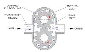
When the toothed wheels inside the casing section turn, air gets in between and throughout the teeth, creating space. This is the result of a positive uplift of the liquid on its way to the suction pump. The pump will continue to draw in air until it begins to receive liquid through the inner section.
The liquid will be enter into it at atmospheric pressure before becoming trapped between the spaces of two wheels. The viscous liquid will be gradually enter in the direction of output and then towards the out. The pump works effectively even when it is off, but it works more actively when it is proper prime.
In the case of valve relieving, additional protection is install in the gear type revolving pump to prevent any kind of damage to the pipeline or pump. During an emergency, the relieving valve will reduce the additional pressure, protecting the entire system.

Parts of gear pump

1.Drive gear :-The prime mover is connected to the drive gear. It is rotated by the power of the prime mover. The primary mover is the motor.
2.Driven gear :- The driven gear is intermeshed with the drive gear. As the drive gear rotates, the driven gear rotates in the opposite direction.
3.Casing :- The driver and driven gears are both packed inside the gear pump’s casing.The driver and driven gears are both housed within the casing of the gear pump.
4.Suction Side: The section of the gear pump from where fluid enters the gear pump. The Inlet Section is where low-pressure liquid enters the pump.The gear pump section from which fluid enters the gear pump. Low-pressure liquid enters the pump through the Inlet Section.
5.Discharge Side :- The pressurised fluid is delivered to the required area via the discharge side of the gear pumps. The outlet section of the pump discharges high-pressure liquid.
6.Prime Mover: In a gear pumps, the prime mover provides power to the shaft on which the driver gear is mounted. An electric motor, an internal combustion engine, or manual labour could all be used.
Applications of Internal gear pumps
- Used in surfactants and soaps manufacturing
- Pigments, inks, and resins
- Used in food products like animal feed, cocoa butter, corn soups and in many
- Resins and Polymers
- Alcohols and solvents
- Asphalt, Bitumen, and Tar
- Polyurethane foam (Isocyanate and polyol)
- Glycol
Suggested Read: Muff Coupling
What are main advantages and disadvantages of the gear pumps?
Factors influencing gear pump efficiency
In general, gear pumps are very efficient, especially in high-pressure applications.
The following factors influence pump efficiency:
1.Clearances:-Geometric clearances at the gear ends and outer diameters allow for leakage and back flow. Greater clearances, on the other hand, can sometimes help to reduce hydrodynamic friction and improve efficiency.
2.Backlash:-Due to high backlash between gears, fluid leakage is also possible. This, however, aids in preventing energy loss caused by fluid trapped between gear teeth (known as pressure trapping).
Read :-Hydraulic pump


